I have started re-learning C using the "C Head First Book" after doing it at university a number of years ago and decided to purchase an Ardunio (Well Genunio as I am not in the USA). The first lab in the book was to create a moisture sensor for detecting if a plant needed watering and write the output to the serial port to display on the PC. I purchased quite a few components from Banggood including this 4 bit 7 segment display. I found some driver code via the bang good forums which worked but decided to write my own as I wasn't a fan of how it was written. It is also far better to write it from scratch if you want to learn exactly how it works and not just pass variables into a pre-defined function.
How the 7 segment display works
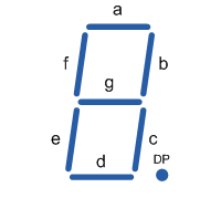
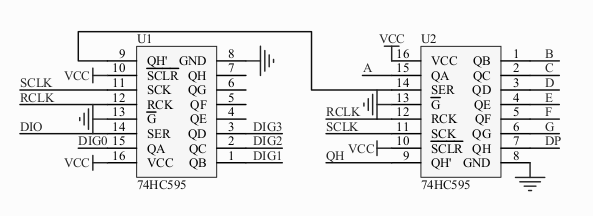
The banggood display module has two 74HC595 shift registers on the back which controls the individual led segments on the display. A shift register is simply put a way of expanding the pins of a micro-controller, this means the display only needs 3 input PINS. The display is a 4 bit display because it has four blocks of 7 segments (excluding the dot). The schematic diagram I found for the display shows which pins of shift registers control which segments on the display. The display segments are labelled using letters A-G and DP. The below image shows which letters correspond to which segment.
The display has 5 wires to connect; VCC (5 or 3.3v), GND, DIO (Data PIN), SCLK (Serial Clock) and RCLK (Register Clock). The pins from QA-QH are the output pins on the shift registers. The first step is to set the register clock low which allows data to be sent to registers. Then the serial clock is set to low, data is sent in (say bit 0 or 1) and the serial clock is set to high. When the serial clock is set to high it shifts the values to the right. This is repeated as many times as needed to get the right data in the chip (0's and 1's), once all the data is in the right place then the register clock is set to high. This copies all the data to the display registers to be displayed; effectively turning on the display. This is a brief explanation but more information can be found here The 74HC595 Register.
 Sending information to the display
We can use the arduino shiftout function to shift bits to the display and the digitalWrite function to set the pins high/low. The display is made up of 8 segments and each one is turned on/off by a bit. The first bit sent to the register is segment 'A' at the right hand side and segment 'DP' at the left most side. For example this byte will be sent to display 'C'. The zero's are on and the 1's are off because the display is a common anode display (CAD).
C = 0b11000110
There are two 74HC595 shift registers so we need to send 16 bits (two bytes) to the chip. The diagram above shows the first register controls which display unit to show the information on. This is the pins QA, QB, QC and QD while the rest are blank and can be any value. This is not inverted so '1' is now on and '0' is now off.
For example:
0b11111001 will turn on the first (right most) and last (left most) display unit. So it will be "C OFF OFF C".
To display just one C on the right then it will be:
0b11110001
The code
The smallest code required to send a C to the display can be seen below.
//Pin connected to ST_CP of 74HC595 AKA RCLK
short rclk = 4;
//Pin connected to SH_CP of 74HC595 AKA SCLK
short sclk = 6;
//Pin connected to DS of 74HC595 AKA DIO
short dio = 3;

void setup()
{
//set pins to output so you can control the shift register
pinMode(rclk, OUTPUT);
pinMode(sclk, OUTPUT);
pinMode(dio, OUTPUT);
Serial.begin(9600);
}

void loop()
{
digitalWrite(rclk, LOW); //Set the register clock to low

shiftOut(dio, sclk, MSBFIRST, 0b11000110); //This function will loop through internally turning the serial clock low and high
//while it passes all the data. This will send a C, segments A,D,E,F are on via the 0.

shiftOut(dio, sclk, MSBFIRST, 0b00000001); //The right most 4 bits control the displays. This will turn on the right hand one only.
digitalWrite(rclk, HIGH); //Clocks the register high effectively turning on the display

}
This is not useful on it's own. The code needs to be able display lots of different values. This is where it got a little tricky to work out until I got the pen and paper out and could draw out how C handles arrays and pointers. The first step is a function that returns the required byte for the values 0-F (Hex). I decided to create a switch statement. The first part check if it is a capital C or lower case because I wanted to be able to display temperature. If it is not a lower case C then it capitalises it to match on the switch statement.
byte getBits(char val)
{
  byte b;

  if(val != 'c')
  {
      val = toupper(val);
  }

  switch(val)
  {
    case 'A':
      b = 0b10001000;
      break;
    case 'B':
      b = 0b10000011;
      break;
    case 'C':
      b = 0b11000110;
      break;
    case 'c':
      b = 0b10100111;
      break;
    case 'D':
      b = 0b10100001;
      break;
    case 'E':
      b = 0b10000110;
      break;
    case 'F':
      b = 0b10001110;
      break;
    case '0':
      b = 0b11000000;
      break;
    case '1':
      b = 0b11111001;
      break;
    case '2':
      b = 0b10100100;
      break;
    case '3':
      b = 0b10110000;
      break;
    case '4':
      b = 0b10011001;
      break;
    case '5':
      b = 0b10010010;
      break;
    case '6':
      b = 0b10000010;
      break;
    case '7':
      b = 0b11111000;
      break;
    case '8':
      b = 0b10000000;
      break;
    case '9':
      b = 0b10010000;
      break;
    case '.':
      b = 0b01111111;
      break;
    case '-':
      b = 0b10111111;
      break;
    default:
      b = 0b11111111;
  }

  return b;
}
This still limits us to one number/letter at a time. Just modify the loop function:
char toShow[] = "2";

      digitalWrite(rclk, LOW);

      shiftOut(dio, sclk, MSBFIRST, getBits(toShow[0]));

      shiftOut(dio, sclk, MSBFIRST, digitalPins[s]);

      digitalWrite(rclk, HIGH);
We can display multiple values at once by using the following code.
//Pin connected to ST_CP of 74HC595 AKA RCLK
short rclk = 4;
//Pin connected to SH_CP of 74HC595 AKA SCLK
short sclk = 6;
////Pin connected to DS of 74HC595 AKA DIO
short dio = 3;

void setup()
{
  //set pins to output so you can control the shift register
  pinMode(rclk, OUTPUT);
  pinMode(sclk, OUTPUT);
  pinMode(dio, OUTPUT);
  Serial.begin(9600);
}

byte getBits(char val)
{
  byte b;

  val = toupper(val);
  switch(val) //Removed to reduce size of post. Take copy from above.

  return b;
}

void loop()
{
    //Serial.println(0b11111000);

    // take the latchPin low so
    // the LEDs don't change while you're sending in bits

    const char *digitalPins = "8421";
    for(unsigned short s = 0; s <4; s++)
    {
      digitalWrite(rclk, LOW);
      // shift out the bits:

      shiftOut(dio, sclk, MSBFIRST, getBits([s]));

      shiftOut(dio, sclk, MSBFIRST, digitalPins[s]);

      //take the latch pin high so the LEDs will light up:
      digitalWrite(rclk, HIGH);

//      delay(2000);
    }
    // pause before next value:
//    delay(5);
}
You probably noticed this line:
const char *digitalPins = "8421";
This is used instead of the second byte. The numbers control the display to light up, 8 is left and 1 is right.
The above code will work correctly however it will only justify the values left which doesn't look quite right to me, I found code elsewhere but that seemed a bit excessive. I wrote some code to reverse the value string and then reversed the digital pin values. Modify the loop to look like this:
void loop()
{
    //Serial.println(0b11111000);

    // take the latchPin low so
    // the LEDs don't change while you're sending in bits:

    char *toShow = "-243";
    size_t len = strlen(toShow);
    char *t = toShow + len-1;
    char reversed[sizeof(toShow)];
    short num = 0;

    while(t >= toShow)
    {
      reversed[num] = *t;
      t = t - 1;
      num++;
    }

    const char *digitalPins = "1248";
    for(unsigned short s = 0; s <4; s++)
    {
      digitalWrite(rclk, LOW);
      // shift out the bits:

      shiftOut(dio, sclk, MSBFIRST, getBits(reversed[s]));

      shiftOut(dio, sclk, MSBFIRST, digitalPins[s]);

      //take the latch pin high so the LEDs will light up:
      digitalWrite(rclk, HIGH);

//      delay(2000);
    }
    // pause before next value:
//    delay(5);
}
You should now have working code that can be used to display values on the display. I have created an arduino library which you can add to your IDE by simply copying the folder to the libraries directory and then "Sketch - Manage Library".
Ardunio Library
This has been converted to C++ as instructed in the Ardunio documentation.
The code has now been moved to a GitHub Repo.
Example Use Code
Display Value
#include <FourBitDisplay.h>
#include <string.h>

FourBitDisplay fbd(4,6,3);

void setup()
{
}

void loop()
{
  char *val = "34";
  short arraySize = strlen(val);
  char *just = "r";
  fbd.printToDisplay(val,arraySize,just);
}
Temp Monitor (DS18B20)
I'll write a post about this soon but here the code.
#include <DallasTemperature.h>
#include <OneWire.h>
#include <FourBitDisplay.h>
#include <stdio.h>

FourBitDisplay fbd(8,4,3);

#define ONE_WIRE_BUS 2
float temp;
short y = 0;
DeviceAddress Probe01 = { 0x28, 0xFF, 0x97, 0xAA, 0xC2, 0x15, 0x01, 0x4D };

// Setup a oneWire instance to communicate with any OneWire devices
// (not just Maxim/Dallas temperature ICs)
OneWire oneWire(ONE_WIRE_BUS);

// Pass our oneWire reference to Dallas Temperature.
DallasTemperature sensors(&oneWire);

void setup()
{
  // start serial port
  Serial.begin(9600);

  // Start up the library
  sensors.begin();
  sensors.setResolution(Probe01, 11);
}

void loop()
{
  if(y == 3) //8Mhz clock 3 works best and 5 on 16Mhz clock. For brightness/flickering
  {
    sensors.setWaitForConversion(false);  // makes it async
    sensors.requestTemperatures();
    sensors.setWaitForConversion(true);
    temp = sensors.getTempC(Probe01);
    y=0;
  }
    y++;

  char buf[4];

  if(temp < 100.0 && temp > -9.9)
  {
    dtostrf(temp,4, 2, buf); //Convert from float to char array
  }
  else
  {
    dtostrf(temp,4, 1, buf); //Convert from float to char array
  }

  char *val = buf;
  short arraySize = strlen(val);
  char *just = "r";
  fbd.printToDisplay(val,arraySize,just);
}
Moisture Sensor
The first part of the code is for interrupts to stabilise the display because of the number of value changes in the moisture function. This means the function is only called every half a second.
#include <FourBitDisplay.h>
#include <stdio.h>
int moistLevel = 0; //Global var
int timer1_counter;
void getMoistLevel();
FourBitDisplay fbd(4,6,3);
void setup() {
// put your setup code here, to run once:
pinMode(13, OUTPUT);
Serial.begin(9600);
// initialize timer1
noInterrupts(); // disable all interrupts
TCCR1A = 0;
TCCR1B = 0;
// Set timer1_counter to the correct value for our interrupt interval
//timer1_counter = 64911; // preload timer 65536-16MHz/256/100Hz
//timer1_counter = 64286; // preload timer 65536-16MHz/256/50Hz
timer1_counter = 34286; // preload timer 65536-16MHz/256/2Hz
TCNT1 = timer1_counter; // preload timer
TCCR1B |= (1 << CS12); // 256 prescaler
TIMSK1 |= (1 << TOIE1); // enable timer overflow interrupt
interrupts(); // enable all interrupts
}
ISR(TIMER1_OVF_vect) // interrupt service routine
{
TCNT1 = timer1_counter; // preload timer
getMoistLevel();
}
void getMoistLevel()
{
moistLevel = analogRead(A1);
}
void loop()
{
char buf[4];
sprintf(buf, "%d", moistLevel);
char *val = buf;
char *just = "r";
fbd.printToDisplay(val,just);
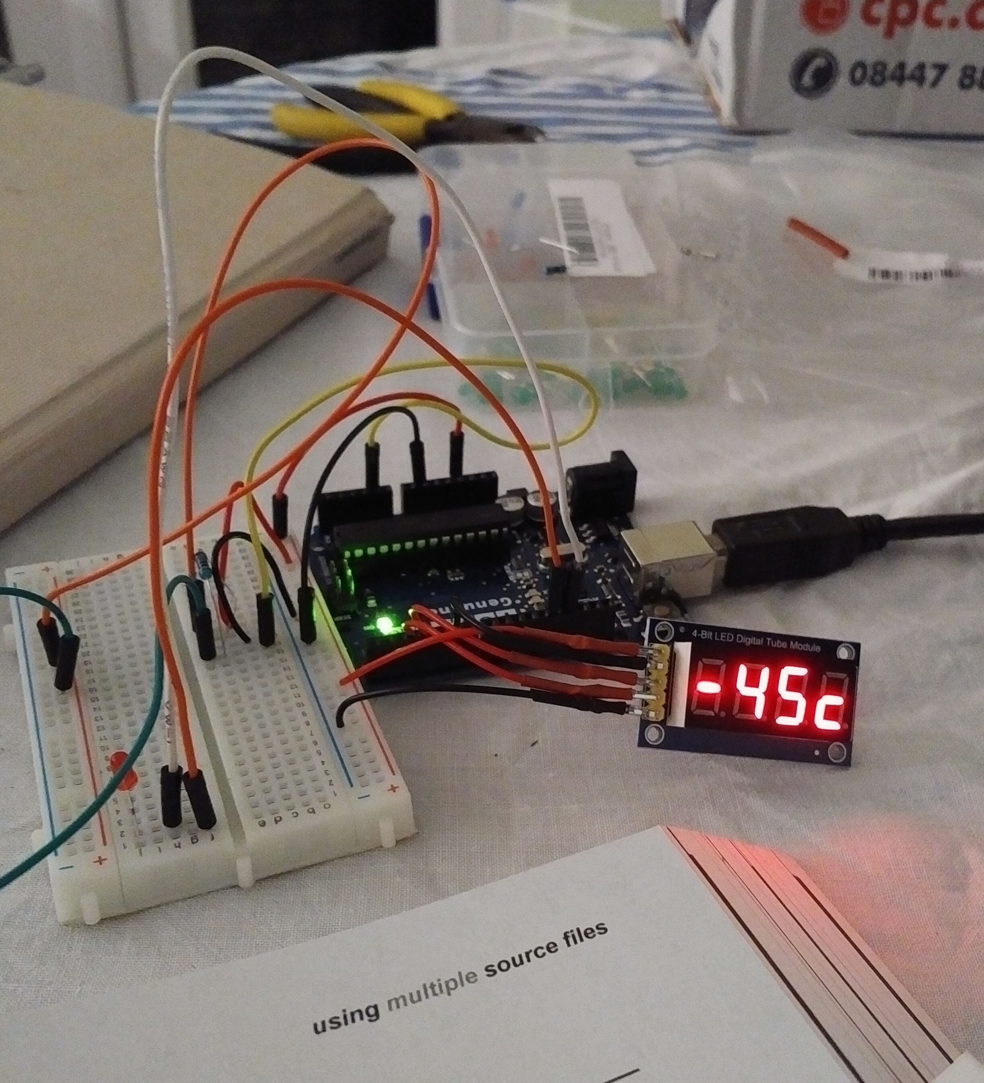
}Finally....What it looks like

Comments powered by Disqus.