Introduction
This post will be extensive so will be separated into 3 parts to make it easier to write and read. I have spent the last couple of months developing a weather station; both for the fun of it and to improve my understanding of the C programming language. The weather station will perform quite a few tasks. It comes in 3 separate bits; several remote sensors that transmit their temperature, location and battery status over an RF link, a receiver module that receives the data over the RF link and the raspberry pi main station which talks over I2C to the receiver unit to get the data. The raspberry pi then processes this information to display on an LCD screen. It has five buttons; one switches between all remote sensors and it's self, 2nd switches between the data&time, IP address and WiFi signal strength, 3rd switches between Celsius and Fahrenheit, 4th turns the display backlight on/off and 5th safely turns the raspberry pi off. All of the code is written in C, both the raspberry pi and arduino.
Please note this does not explain the code line by line and assumes you have an understanding of the "C" programming language. I give solutions to problems I came across and a overall explanation of the code. Hopefully you will find this useful but please comment if you have any queries.
Part One: Arduino Based Remote Sensors
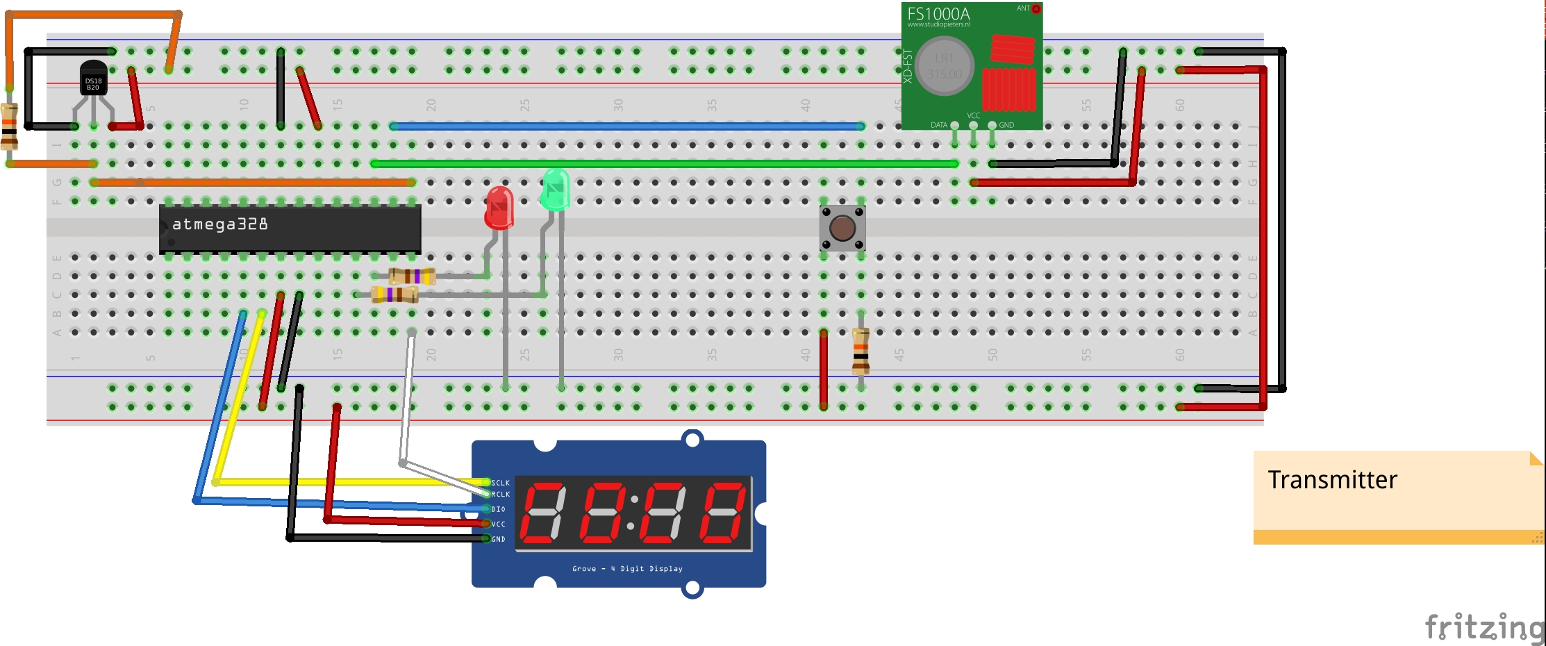
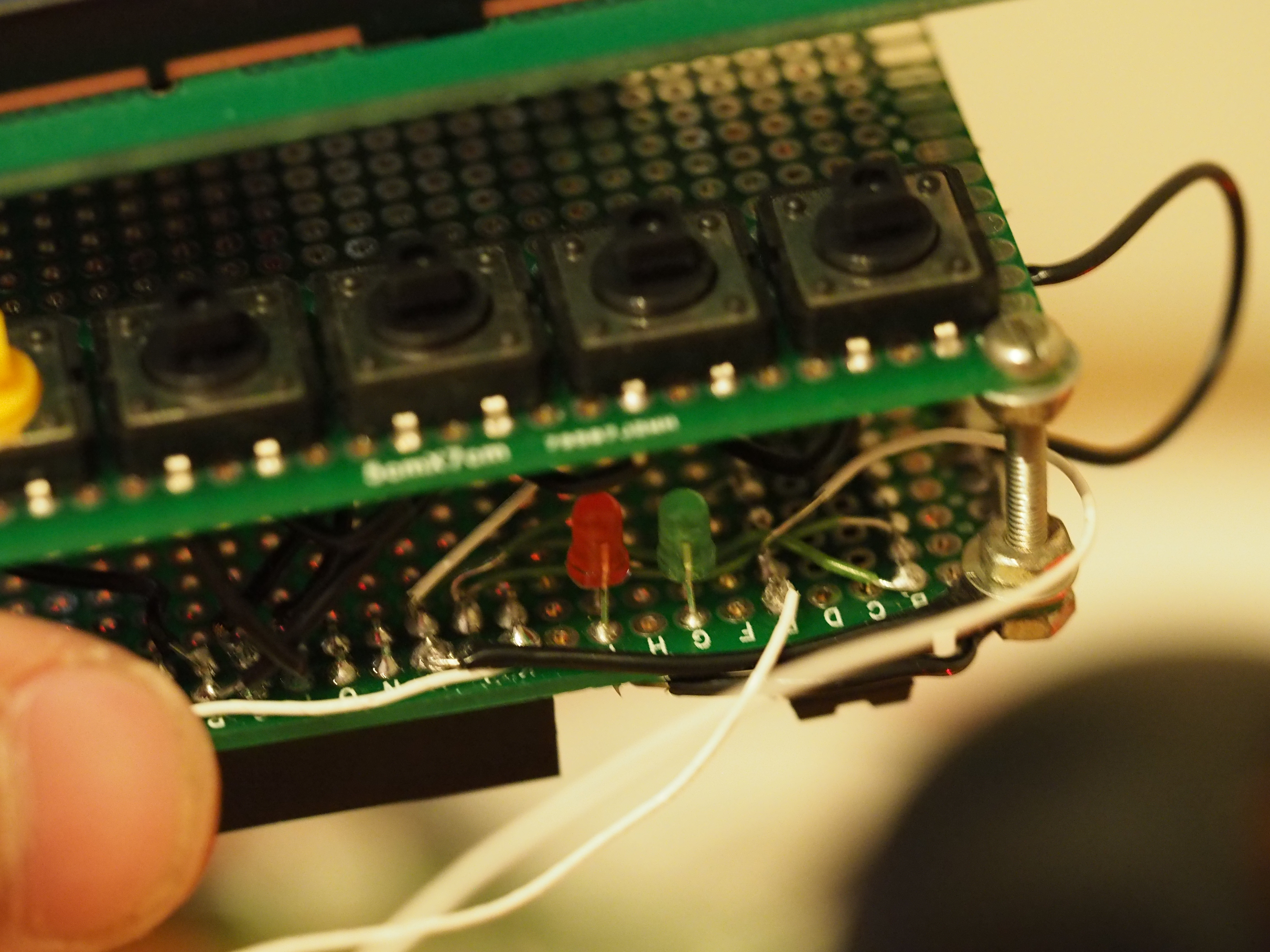
The remote sensor has several parts. A 7 segment display, a button to switch between display on/off, Celsius, Fahrenheit and battery, power module, radio transmitter, two LEDs and the Atmega 328p (Arduino microcontroller, Arduino is used as a programmer only). I bought most of the parts from banggood.com as I found them cheaper, free delivery from China can take a while but they have a few of their things in Europe which arrives quicker.
Parts:
Fritzing Diagram
 To program the chip externally using an Arduino please see here
The Code
#include <DallasTemperature.h>
#include <OneWire.h>
#include <FourBitDisplay.h>
#include <stdio.h>
#include <Vcc.h>
#include <VirtualWire.h>
#include <Thread.h>
#include <ThreadController.h>

//Definitions
#define ONE_WIRE_BUS 9

//****Class declarations
FourBitDisplay fbd(8,4,3);
Thread myThread = Thread();
Thread battCheck = Thread();
Thread tempCheck = Thread();

//****Constant values
const int buttonPin = 10;
const float VccMin   = 0.0;           // Minimum expected Vcc level, in Volts.
const float VccMax   = 5.0;           // Maximum expected Vcc level, in Volts.
const float VccCorrection = 1.0/1.0;  // Measured Vcc by multimeter divided by reported Vcc
Vcc vcc(VccCorrection);
const int lowBattLED = 6; //Pin of connected RED LED
const int TransLED = 5; //Pin of connected RED LED
const int transmit_pin = 11; //RF Transmit PIN

//Other declarations, Button information
int buttonState;              // the current reading from the input pin
int lastButtonState = LOW;   // the previous reading from the input pin
int displayValToShow = 0;
// the following variables are long's because the time, measured in miliseconds,
// will quickly become a bigger number than can be stored in an int.
long lastDebounceTime = 0;  // the last time the output pin was toggled
long debounceDelay = 200;    // the debounce time; increase if the output flickers

//Other declarations, Temperature readings
float temp, perBattLeft;

struct sensor_Data
{
  int temperature;
  char sensorID[10] = "BackBed";
  int perBatt;
};
sensor_Data sd;

//Serial number of each probe connected. Only Probe 2 is connected to this circuit.
DeviceAddress Probe01 = { 0x28, 0xFF, 0x97, 0xAA, 0xC2, 0x15, 0x01, 0x4D };
DeviceAddress Probe02 = { 0x28, 0xFF, 0xB9, 0xEA, 0x21, 0x16, 0x04, 0xBE };

// Setup a oneWire instance to communicate with any OneWire devices
// (not just Maxim/Dallas temperature ICs)
OneWire oneWire(ONE_WIRE_BUS);

// Pass our oneWire reference to Dallas Temperature.
DallasTemperature sensors(&oneWire);

void transmitTemp()
{
  sd.temperature = (int)(temp*100);
  sd.perBatt = (int)(perBattLeft*100);

  digitalWrite(TransLED, HIGH);
  vw_send((uint8_t *)&sd,sizeof(sd));
  vw_wait_tx(); // Wait until the whole message is gone
  digitalWrite(TransLED, LOW);
}

void convertFloatToChar(float temp, char buf[4])
{
  if(temp < 100.0 && temp > -9.9)
  {
    dtostrf(temp,4, 2, buf); //Convert from float to char array
  }
  else
  {
    dtostrf(temp,4, 1, buf); //Convert from float to char array
  }
}

void checkBatt()
{
  //Check the battery percentage remaining for the LED
  perBattLeft = vcc.Read_Perc(VccMin, VccMax);
  if(perBattLeft <20)
    digitalWrite(lowBattLED, HIGH);
}

void checkTemp()
{
    sensors.setWaitForConversion(false);  // makes it async
    sensors.requestTemperatures();
    sensors.setWaitForConversion(true);
    temp = sensors.getTempC(Probe02);
}

void setup()
{
  // start serial port
  Serial.begin(9600);

  randomSeed(analogRead(A0));  //initialize the random number generator with
                               //a random read from an unused and floating analog port
                               //to be able to transmit over rf at random times
  unsigned long randNumber = random(10,20); //1 to 2 minutes to delay

  // initialize the pushbutton pin as an input:
  pinMode(buttonPin, INPUT);

  //Low battery PIN setup and Transmit LED
  pinMode(lowBattLED, OUTPUT);
  pinMode(TransLED, OUTPUT);

  //Transmit Stuff
  vw_set_tx_pin(transmit_pin);
  vw_setup(2000);       // Bits per sec

  // Start up the library
  sensors.begin();
  sensors.setResolution(Probe02, 11);

  //This turns off the display so there is no initial rubbish on the display upon power on!
  fbd.printToDisplay("////",4,"r");

  //Thread stuff so I can transmit every so often
  myThread.enabled = true; // Default enabled value is true
  myThread.setInterval(randNumber*1000); // Setts the wanted interval to be 10ms
  myThread.onRun(transmitTemp);

  battCheck.enabled = true; // Default enabled value is true
  battCheck.setInterval(120000); // Setts the wanted interval to be 10ms
  battCheck.onRun(checkBatt);
  perBattLeft = vcc.Read_Perc(VccMin, VccMax); //Check now upon boot so it is not zero for two mins

  tempCheck.enabled = true; // Default enabled value is true
  tempCheck.setInterval(8); // Setts the wanted interval to be 10ms
  tempCheck.onRun(checkTemp);
}

void loop()
{
  // read the state of the pushbutton value:
  buttonState = digitalRead(buttonPin);

  if(tempCheck.shouldRun())
  {
    tempCheck.run();
  }
  if(myThread.shouldRun())
  {
    // Yes, the Thread should be runned, let's run it
    myThread.run();
  }
  if(battCheck.shouldRun())
  {
    // Yes, the Thread should be runned, let's run it
    battCheck.run();
  }

  if (buttonState == HIGH && lastButtonState == LOW && millis() - lastDebounceTime > debounceDelay)
  {
    displayValToShow++;
    if(displayValToShow > 3)
    {
      displayValToShow = 0; //Cycle round 3 times and fourth turn off display again
    }
    lastDebounceTime = millis();
  }

  char buf[4]; //Later on for showing on display
  char *val;
  char *just = "r";
  float f;

  if(displayValToShow == 0)
  {
    val = "////";
  }
  else if(displayValToShow == 1)
  {
    convertFloatToChar(temp,buf);
    val = buf;
  }
  else if(displayValToShow == 2)
  {
    f = temp*1.8+32; //Convert to F
    convertFloatToChar(f,buf);
    val = buf;
  }
  else
  {
    convertFloatToChar(perBattLeft,buf);
    val = buf;
  }

  short arraySize = strlen(val);
  fbd.printToDisplay(val,arraySize,just);
  lastButtonState = buttonState;
}
Please note: The 7 Segment display driver used I have written so is available on a previous post or via the Arduino community website.
So what does the code do?
Setup:
This sets up the button, threading stuff (not true threads, an implementation to run code blocks at specified times), pins and the RF transmitter. There are three threads, one for transmitting the data over RF, second for gathering the battery information and third for checking the temperature. Pay particular attention to the timings; the transmitting thread runs at a random time so it minimises the chance of a collision with another probe, the battery runs every 2 minutes to save battery life and it is not necessary to run any more. The most important thread is "tempCheck", this is because this action takes 2ms to complete (Reduced from default 750ms) and the 7 segment display needs a value to be constantly written to it otherwise it would go off. This makes the display sensitive to timings, if there is a delay in the code then the display will go off and a small delay like 50ms will make the display flicker. I experimented for a while but found the optimal solution for me. If the code didn't check the temperature at all then the display would be full brightness without any flicker at all, but this would be pointless. If I made the temperature check only happen every 10 seconds then it would be too slow to react and you would see a noticeable flick. I chose to check every 8ms because the display is constant with no visible flicker although it is not quite full brightness and it reacts instantly to temperature change. If you run the chip at 16mhz instead of 8 then the timings would be different. The rest of the setup code should pretty much explain itself.
Loop:
The lines 144 - 170 make the push button a switch so it switches the display between 4 modes and controls the timing of the threads. The button increments a displayValToShow value when pushed and further down in the loop a series of "ifs" checks the value to determine what to send to the display function. I noticed that using a switch statement here makes the code neater but performs noticeably slower as the display flickers. It is possible the compiler is not optimising the switch correctly. The code then calls a function to convert the float values to a char array so they can be displayed by the 7 segment display as the function takes a char array. After the if statements have been called then a function call prints the char array on the display. Please note "////" is sent to the display as this turns the display "off".
Checking Temp Quickly:
This was an issue when using a 7 segment display as noted above. The display needs to be constantly updated fast enough that the human eye can't see any flicker. The display is not constantly on like an LCD but a series of pulses. For more information see my previous post here. The DS18B20 temperature probe takes 750ms to read a value in it's full accuracy mode and 93ms in its least accurate. Both of these times are slow enough to visibly pause the display but I found a way of asynchronously getting the reading which reduces the time to 2ms with any level of accuracy. I was able to tweak how often to fetch the temperature to every 8ms which meant the display did not flicker.
Sending the Temp etc over RF:
I wanted to send several bits of data over the RF radios, including temperature, battery status and sensor ID. The easiest and neatest way of doing this was sending a structure, but the excellent Virtual Wire library function "vw_send" requires bytes to be sent. To send a structure the structure needs to be cast into a "uint8_t *" which would send it over as bytes. I also blink a green LED to show transmission.
To prevent multiple sensors transmitting at the same time then I have made them choose a random time upon power on using the analogue pin of the atmega as a seed. I decided to choose between 1-2mins however the code above is development code and is between 10 and 20 seconds. This is located on lines 107 & 129.
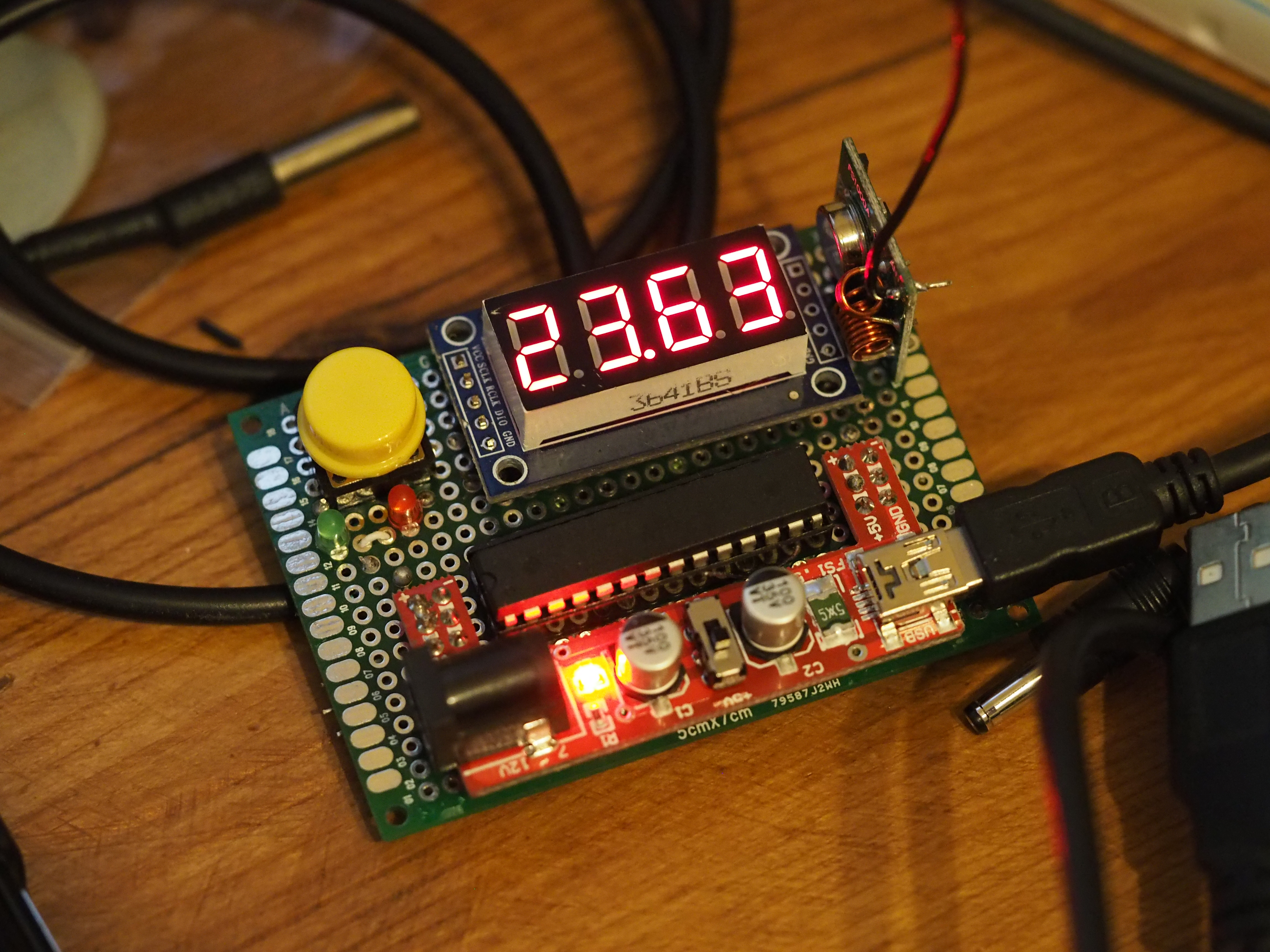
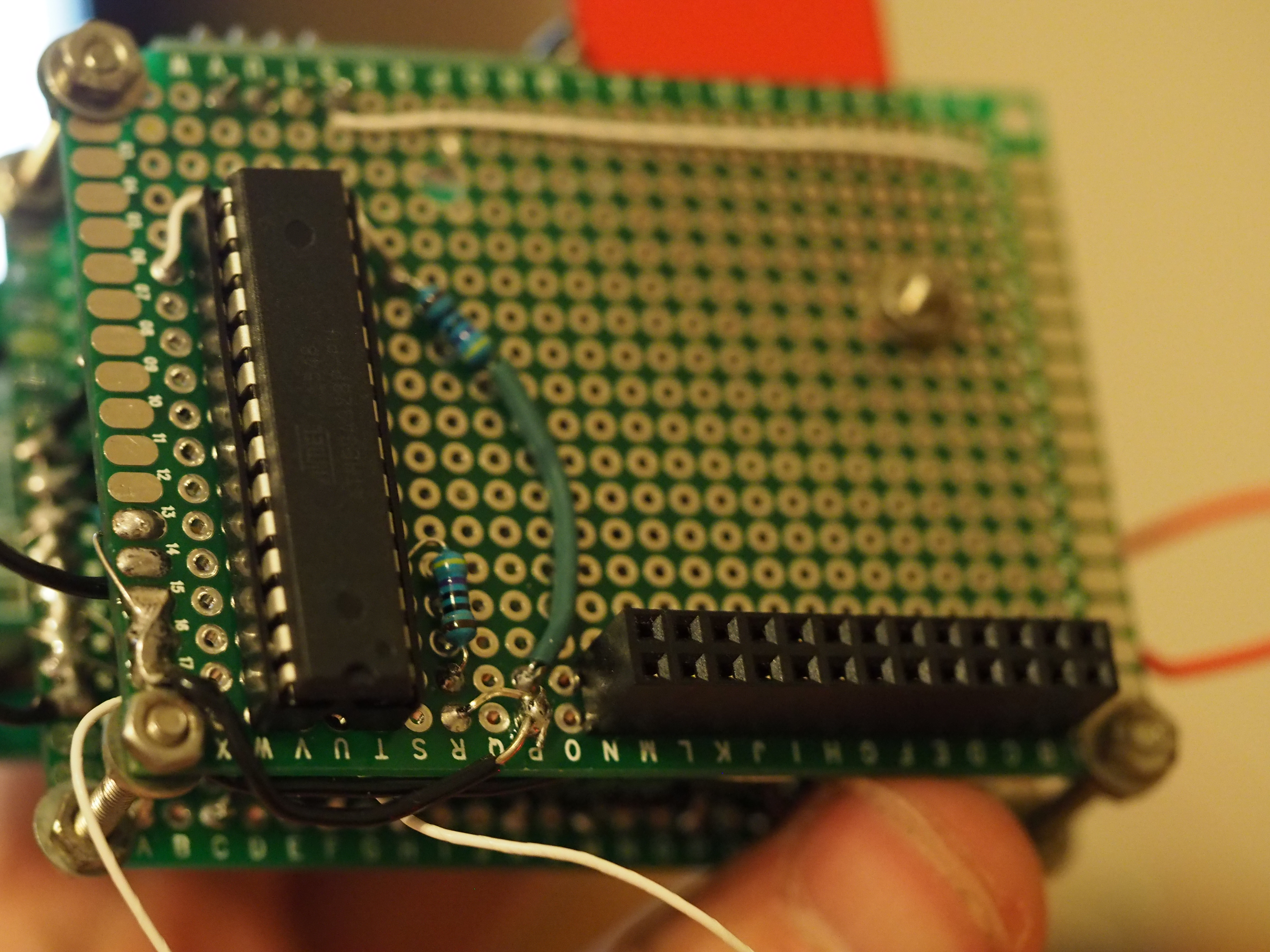
Device Prototype
I built this using a breadboard and then built another sensor using a perf board. The next step would be a printed circuit board as this would be more professional, reliable and quicker to build. Here are some pictures.
To Do:
There are a few things I still need to implement.
- Tidy up the code to production
- Optimise for battery use
- Add diode to finished circuit so I can use a battery or mains
- Possibly add a voltage regulator to keep it at 5v when running off a battery
- Possibly add a voltage step-up device for the transmitter so it can operate at 12v to improve its range
- Get printed PCB
- Build a case
Part Two: Arduino Based Receive Sensor module for Raspberry Pi
This module is designed to receive the RF transmissions and store them in a temporary structure. The raspberry pi will ask the module to send the data over a i2c connection when asked.
Fritzing Diagram:
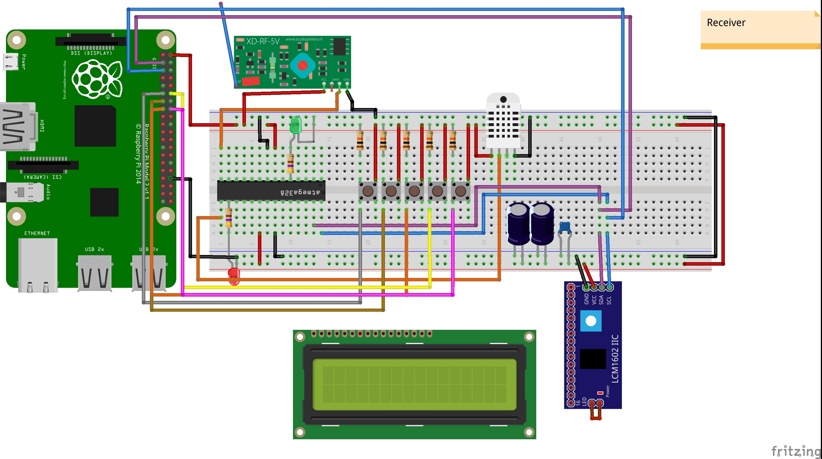
The module has five buttons; from left to right: Switch Sensor, (Switch between Date&Time, IP, WiFi Signal), Switch between Celsius & Fahrenheit, Turn Display LED off and Safely Shutdown. As you can see from the diagram above the buttons are attached to the raspberry pi directly as well as the LCD screen (Please note the LCD is not attached on the diagram as mine is soldered to the i2c chip already so I am just showing the connections from the i2c chip). These will be explained in the next section but I mention them here because I soldered together a module which plugs directly onto the raspberry pi as one unit.
The Atmega 328p chip runs a loop checking to see if the receiver module has received a valid signal and if it has then it copies it into the sensor structure. The code checks the temperature and humidity of the DHT22 sensor every 2 seconds and copies into the correct structure. The code only performs something else when the raspberry pi sends a request via the i2c interface; either a 1 or 0. Depending on the number then the chip will send back the local data or remote sensor data. A union is used so the structure can be sent as a char array; a uint16_t should be used here for consistency and not just an int as the raspberry pi needs to use a uint16_t to rebuild the structure correctly. This is because the Atmega 328p stores an int as 2 bytes while the raspberry pi stores an int as 4 bytes.
The Code:
#include <VirtualWire.h>
#include <stdio.h>
#include <dht.h>
#include <Thread.h>
#include <ThreadController.h>
#include <Wire.h>

#define DHT22_PIN 9
#define SLAVE_ADDRESS 0x04

dht DHT;
Thread myThread = Thread();

//Constant values
const int receive_pin = 8;
const int receive_LED = 3;
const int dhterror_LED = 10;

//Globals
char result[4];
float tempFromSensor, perBattLeft;
float t; //temp value
int chk;
long errorC = 0;
long okC = 0;
uint8_t whichStructToSend = 0;

struct sensor_Data
{
  uint16_t temperature;
  char sensorID[10];
  uint16_t perBatt;
}tempSensorValues;

struct local_Data
{
  uint16_t temperature;
  char sensorID[10];
  uint16_t humidity;
}local;

union sensorStructToSendViaI2C
{
  sensor_Data tempSensorValues;
  byte packet[sizeof(sensor_Data)];
};
sensorStructToSendViaI2C ssts;

union localStructToSendViaI2C
{
  local_Data local;
  byte packet[sizeof(local_Data)];
};
localStructToSendViaI2C lsts;

void getDHT22()
{
  chk = DHT.read22(DHT22_PIN);
  switch (chk)
    {
    case DHTLIB_OK:
        digitalWrite(dhterror_LED, LOW);
        lsts.local.temperature = (uint16_t)(DHT.temperature*100);
        lsts.local.humidity = (uint16_t)(DHT.humidity*100);
        okC++;
        break;
    default:
        digitalWrite(dhterror_LED, HIGH);
        errorC++;
        break;
    }
}

// callback for sending data
void sendData()
{
 //Wire.write((byte *) &tempSensorValues, sizeof tempSensorValues);
 if(whichStructToSend == 1)
 {
  Wire.write(ssts.packet, sizeof(sensor_Data));
 }
 else
 {
  Wire.write(lsts.packet, sizeof(local_Data));
 }

// int len = sizeof(struct sensor_Data);
// Serial.println(len);
// char test[len];
// memcpy(test, &tempSensorValues, len);
//Wire.write(test, len);

 //memcpy(&doesitwork, test, len); Copies to another struct variable

}
void receiveData(int numBytes)
{
 int number;
 while(Wire.available())
 {
  number = Wire.read();
  if (number == 0)
  {
    whichStructToSend = 0;
  }
  else
  {
    whichStructToSend = 1;
  }
 }
}

void setup()
{
  delay(1000);
  Serial.begin(9600);
  pinMode(receive_LED, OUTPUT);
  pinMode(dhterror_LED, OUTPUT);

  //RF Setup
  vw_set_rx_pin(receive_pin);
  vw_setup(2000);   // Bits per sec
  vw_rx_start();

  //Thread stuff so I can transmit every so often
  myThread.enabled = true; // Default enabled value is true
  myThread.setInterval(2000); // Setts the wanted interval to be 10ms
  myThread.onRun(getDHT22);

  // initialize i2c as slave
 Wire.begin(SLAVE_ADDRESS);

 // define callbacks for i2c communication
 Wire.onReceive(receiveData);
 Wire.onRequest(sendData);

 strcpy(lsts.local.sensorID,"Here");
}

void loop()
{
  uint8_t buf[VW_MAX_MESSAGE_LEN];
  uint8_t buflen = VW_MAX_MESSAGE_LEN;

  if (vw_get_message(buf, &buflen)) // Non-blocking
  {
    int i;

    digitalWrite(receive_LED, HIGH); // Flash a light to show received good message

    // Message with a good checksum received, dump it.

    if(buflen == sizeof(sensor_Data)); //If the structures are the same size then copy data into structure
    {
      memcpy(&ssts.tempSensorValues, buf, sizeof(sensor_Data));
    }

//    for (i = 0; i < buflen; i++)
//    {
//        result[i] = (char)buf[i];
//    }
//    t = atoi(result);
    tempFromSensor = ((float)ssts.tempSensorValues.temperature/100);
    perBattLeft = ((float)ssts.tempSensorValues.perBatt/100);

    delay(100);
    digitalWrite(receive_LED, LOW);
  }
  if(myThread.shouldRun())
  {
    // Yes, the Thread should be runned, let's run it
    myThread.run();
  }


}
Photos:
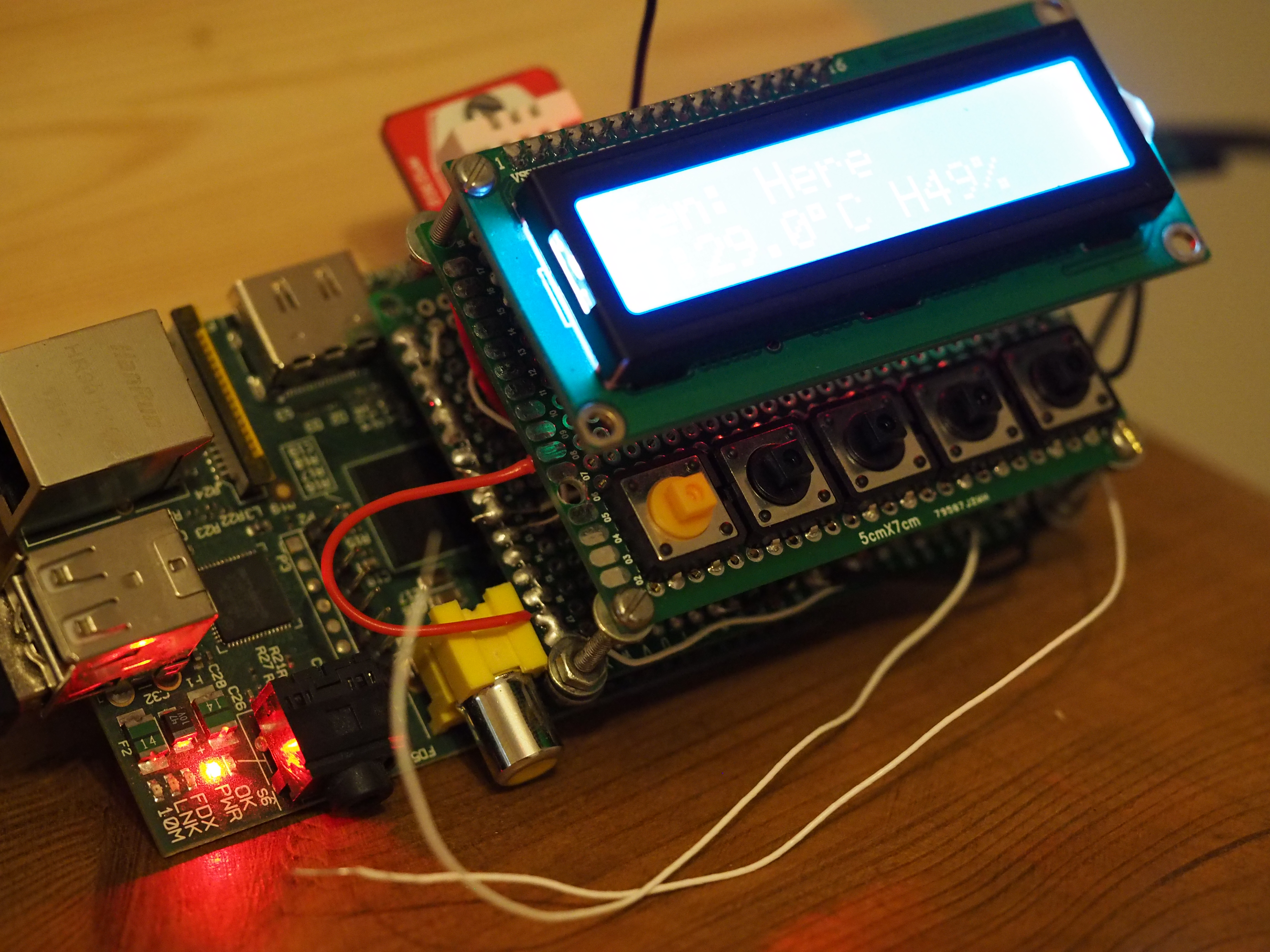
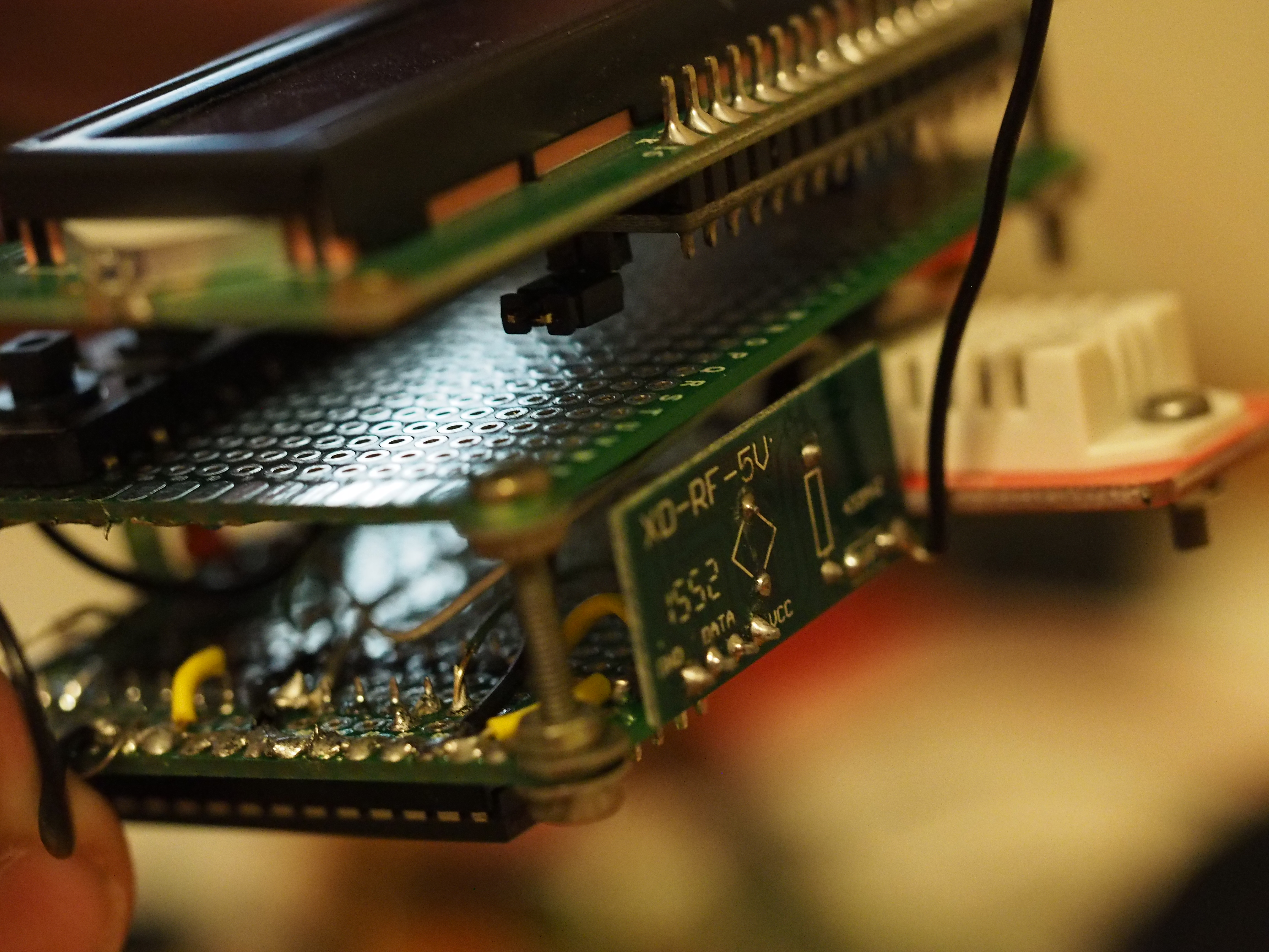
As you can see I decided to build it as a two tier board with small nuts holding them apart. This was easier to build and mount the LCD. I will move the DHT22 module to the top board as it gets affected by the raspberry pi's heat and the second board is cooler, I will also extend the LED's if I put it in a case.
Part Three: Raspberry Pi C code for the central weather station
This is where all the intelligence happens. The code has a view bugs in it still however they do not effect the usage of the weather station itself. As the explained earlier the buttons perform the following functions: from left to right: Switch Sensor, (Switch between Date&Time, IP, WiFi Signal), Switch between Celsius & Fahrenheit, Turn Display LED off and Safely Shutdown. The code is quite large and has many threads to enable all the buttons and sensor functions to work simultaneously. There are three "c" files and one header file. The code does use the wiringPi library and therefore requires root to run. I'll start with the smallest file first; the header file.
Header File:
This is pretty small and simple to understand. The code should explain itself, the functions will be explained later on.
#include <string.h>
#include <unistd.h>
#include <errno.h>
#include <stdio.h>
#include <stdlib.h>
#include <linux/i2c-dev.h>
#include <sys/ioctl.h>
#include <fcntl.h>
#include <unistd.h>
#include <stdint.h>

struct sensor_Data getStructFromModule(uint8_t structToGet);
void init_i2c();
void lcd_init(short onOff);
void lcd_string(char * message, unsigned char line, short onOff);
void lcd_byte(unsigned char bits, unsigned char mode, short onOff);
void clearLCD(short onOff);

//This needs to be shared across two files. Both the LCD functions and the Arduino Module need to access the same /dev/i2c device.
//It needs to be the same device so it can be thread locked before use otherwise the LCD gets corrupted and won't recover.
extern int file_i2c;
i2c.c Code:
This code opens the i2c device and stores the int used to access it in a global variable. There are functions here to get the data from the chip, either remote sensor information or the local temp probe. The piLock is set to number 2 which is the same as the lock used in another file accessing the i2c device. This means corruption of the i2c devices won't occur.
#include "i2c.h"
// The PiWeather board i2c address
#define Ard_ADDRESS 0x04

//Temp struct to store sensor data from the Atmega module attached to Pi over i2c
struct sensor_Data
{
  uint16_t temperature;
  char sensorID[10];
  uint16_t perBatt;
}temporaryStruct;

//Union so it can be converted from Bytes to a struct. Important to use uint16_t in the struct as the arduino "int" is 2 bytes and not 4 likes the Pi's
//This means the struct data won't be created properly.
union structToSendOverRF
{
  struct sensor_Data temporaryStruct;
  char packet[14];
};
union structToSendOverRF sts;

//The i2c device within the Linux system
static const char *devI2c = "/dev/i2c-0";
int file_i2c; //Store the output of the open command in here. Can be used to access device from then on

void init_i2c()
{
    if ((file_i2c = open(devI2c, O_RDWR)) < 0) //Opens device.
    {
        //ERROR HANDLING: you can check errno to see what went wrong
        printf("Failed to open the i2c bus");
        exit(1);
    }
}

struct sensor_Data getStructFromModule(uint8_t structToGet)
{
piLock(2); //Same lock as in mlcd.c as they both access same device using global variable
    if (ioctl(file_i2c, I2C_SLAVE, Ard_ADDRESS) < 0) //Tell only the device at this address to repsond to any requests.
    {
        printf("Failed to acquire bus access and/or talk to slave.\n");
        exit(1);
    }

    char val[1] = {structToGet};

    write(file_i2c, val, 1); //Writes value to Atmega chip. Code on chip then returns value depending on number (val) sent here.

    usleep(50000); //5ms to allow the arduino module to respond

    read(file_i2c, sts.packet, 14);
piUnlock(2);
  return (sts.temporaryStruct);
}
mlcd.c File:
This file writes information to the 16x2 LCD display. The code was originally quickly written by a colleague of mine (without the device) and I modified it to into more of a library. The code was ported from a Python script I had found. The code is commented and is only basic in terms of functionality. There is no function to move the cursor around or clear only a section of the display for example. I could not find anything written in C for the raspberry Pi so had to quickly make one (with some help).
/***************************************
* Maurices quick port of LCD_I2C.PY to C
* 03/05/16
* Edited by Monotok (Chris)
****************************************/

#include "i2c.h"

// Define some device parameters
#define LCD_ADDRESS 0x3f // I2C device address
#define LCD_WIDTH 16   // Maximum characters per line

// Define some device constants
#define LCD_CHR 1 // Mode - Sending data
#define LCD_CMD 0 // Mode - Sending command

#define LCD_BACKLIGHT_ON 0x08  // On
#define LCD_BACKLIGHT_OFF 0x00  // Off

#define ENABLE 0b00000100 // Enable bit

// Timing constants
#define E_PULSE 500 //micro Seconds
#define E_DELAY 500 //micro Seconds

int length;
unsigned char buffer[60] = {0};

void write_byte(unsigned char address, unsigned char byte)
{
    //----- WRITE BYTES -----
    buffer[0] = byte;
    length = 1;            //<<< Number of bytes to write
    if (write(file_i2c, buffer, length) != length)        //write() returns the number of bytes actually written, if it doesn't match then an error occurred (e.g. no response from the device)
    {
        /* ERROR HANDLING: i2c transaction failed */
        printf("write_i2c Failed to write to the i2c bus.\n");
    }
}

void lcd_toggle_enable(unsigned char bits)
{
  // Toggle enable
  usleep(E_DELAY);
  write_byte(LCD_ADDRESS, (bits | ENABLE));
  usleep(E_PULSE);
  write_byte(LCD_ADDRESS,(bits & ~ENABLE));
  usleep(E_DELAY);
}


void lcd_byte(unsigned char bits, unsigned char mode, short onOff)
{
  unsigned char bits_high, bits_low;
  // Send byte to data pins
  // bits = the data
  // mode = 1 for data
  //        0 for command

  if(onOff == 0)
  {
    bits_high = mode | (bits & 0xF0) | LCD_BACKLIGHT_OFF;
    bits_low = mode | ((bits<<4) & 0xF0) | LCD_BACKLIGHT_OFF;
  }
  else
  {
    bits_high = mode | (bits & 0xF0) | LCD_BACKLIGHT_ON;
    bits_low = mode | ((bits<<4) & 0xF0) | LCD_BACKLIGHT_ON;
  }

  // High bits
  write_byte(LCD_ADDRESS, bits_high);
  lcd_toggle_enable(bits_high);

  // Low bits
  write_byte(LCD_ADDRESS, bits_low);
  lcd_toggle_enable(bits_low);
}

void lcd_init(short onOff)
{
  // Initialise display

      if (ioctl(file_i2c, I2C_SLAVE, LCD_ADDRESS) < 0)
    {
        printf("Failed to acquire bus access and/or talk to slave.\n");
        exit(1);
    }
  lcd_byte(0x33,LCD_CMD,onOff); // 110011 Initialise
  lcd_byte(0x32,LCD_CMD,onOff); // 110010 Initialise
  lcd_byte(0x06,LCD_CMD,onOff); // 000110 Cursor move direction
  lcd_byte(0x0C,LCD_CMD,onOff); // 001100 Display On,Cursor Off, Blink Off
  lcd_byte(0x28,LCD_CMD,onOff); // 101000 Data length, number of lines, font size
  lcd_byte(0x01,LCD_CMD,onOff); // 000001 Clear display

  usleep(E_DELAY);
}

void clearLCD(short onOff)
{
    piLock(2); //Same lock as in i2c.c
    if (ioctl(file_i2c, I2C_SLAVE, LCD_ADDRESS) < 0)
    {
        printf("Failed to acquire bus access and/or talk to slave.\n");
        exit(1);
    }
    lcd_byte(0x01,LCD_CMD,onOff); // 000001 Clear display
    piUnlock(2);
    usleep(E_DELAY);
}

void lcd_string(char * message, unsigned char line, short onOff)
{
  piLock(2); //Same lock as in i2c.c
      if (ioctl(file_i2c, I2C_SLAVE, LCD_ADDRESS) < 0)
    {
        printf("Failed to acquire bus access and/or talk to slave.\n");
        exit(1);
    }
  //Send string to display
  int i;
  lcd_byte(line, LCD_CMD, onOff);

    for(i = 0; i<strlen(message); i++)
    {
        lcd_byte(message[i],LCD_CHR, onOff);
    }
  piUnlock(2);
}
weatherStation.c Code:
This file is far too large to go through the code line by line but I have commented every function with an explanation. Please comment if there is anything you don't understand or think could be improved. The code initualises the button struct's and starts all the threads. Every 5 seconds the value from the Atmega chip is retrieved and processed into the correct struct. The display displays the date/time by default but any press of the button changes that. The sensor values are written to a RAM disk so they can be monitored by Zabbix.
#include "i2c.h"
#include <time.h>
#include <wiringPi.h>
#include <arpa/inet.h>
#include <sys/socket.h>
#include <ifaddrs.h>
#include <unistd.h>
#include <sys/reboot.h>

//For the LCD screen
#define LCD_LINE_1 0x80 // LCD RAM address for the 1st line
#define LCD_LINE_2 0xC0 // LCD RAM address for the 2nd line
#define LCD_LINE_3 0x94 // LCD RAM address for the 3rd line
#define LCD_LINE_4 0xD4 // LCD RAM address for the 4th line

#define _GNU_SOURCE     // To get defns of NI_MAXSERV and NI_MAXHOST

//Weather to get the local data from the arduino chip or remote sensor data. This is passed to a function.
#define GET_LOCAL_DATA 0
#define GET_REMOTE_SENSOR_DATA 1

//This takes advantage of the Linux reboot library. Needed for the button to safely shut down the device.
#define LINUX_REBOOT_CMD_HALT 0xcdef0123

//Other declarations

//Turn the display on or off. 1 is on and 0 is off. Passed as a parameter to the LCD function. Button for controlling backlight manipluates this value.
short displayOnOff = 1;

//Structure containing all the variables for making a push button a switch button. Neater than having multiple versions of the same variable.
struct buttonState
{
    int currentButtonState; // the current reading from the input pin
    int lastButtonState; // the previous reading from the input pin
    long lastDebounceTime; // the last time the output pin was toggled
    long debounceDelay; // the debounce time; increase if the output flickers
    short buttonPin;
    int displayValToShow;   //To cycle round the display
};
struct buttonState sensorBtn; //Button to cycle through the sensor data
struct buttonState dateTimeBtn; //Button for IP Date Time and WiFi Signal
struct buttonState celFar; //Switch between C & F
struct buttonState rebootBtn; //Safely shut down the device.
struct buttonState turnOffLCDBtn; //Turn off the LCD backlight

//Structure to store all the sensor data. Both local and remote. Value is called BattOrHum because it can be either battery percentage or humidity percentage.
//Did not want to create another struct type when it would be exactly the same just with a different variable name.
struct sensor_Data
{
  uint16_t temperature;
  char sensorID[10];
  uint16_t perBattOrHum;
}temporaryStruct; //Temporary data struct to store data recieved from the weather module until it is moved to correct struct

struct sensor_Data outside;
struct sensor_Data outsidePrev; //Stores the previous values for display. This means the main loop will compare to previous value and not refresh the LCD unless necessary
struct sensor_Data loft;
struct sensor_Data loftPrev;
struct sensor_Data shed;
struct sensor_Data shedPrev;
struct sensor_Data garage;
struct sensor_Data garagePrev;
struct sensor_Data frontBed;
struct sensor_Data frontBedPrev;
struct sensor_Data backBed;
struct sensor_Data backBedPrev;
struct sensor_Data lounge;
struct sensor_Data loungePrev;
struct sensor_Data local;
struct sensor_Data localPrev;

//Declarations
void writeTempsToRAMFile(struct sensor_Data *structToWrite);


/**
 * @brief
 * This function takes a structure variable and checks the sensor ID within it. It then compares that against the pre-programmed ID's and once found copies the structure to
 * the correct pre-defined structure for use elsewhere in the program.
 * This locks the data so another thread can't change the data while this function is checking it.
 * This also called another function called "writeTempToRAMFile" which writes the received structure data to a file on a RAM disk so the zabbix monitoring system can graph it.
 * @param s
 *
 *
 */
void cpDataToCorrectStruct(struct sensor_Data *s)
{
    piLock(1);
    writeTempsToRAMFile(s); //This function will write the sensor readings to a temp file in RAM so Zabbix can read
    if(strcmp(s->sensorID,"Here") == 0)
    {
        memcpy(&localPrev,&local,sizeof(local));
        memcpy(&local,&temporaryStruct,sizeof(temporaryStruct));
    }
    else if(strcmp(s->sensorID,"Outside") == 0)
    {
        memcpy(&outsidePrev,&outside,sizeof(outside));
        memcpy(&outside,&temporaryStruct,sizeof(temporaryStruct));
    }
    else if(strcmp(s->sensorID,"Loft") == 0)
    {
        memcpy(&localPrev,&loft,sizeof(loft));
        memcpy(&loft,&temporaryStruct,sizeof(temporaryStruct));
    }
    else if(strcmp(s->sensorID,"Shed") == 0)
    {
        memcpy(&shedPrev,&shed,sizeof(shed));
        memcpy(&shed,&temporaryStruct,sizeof(temporaryStruct));
    }
    else if(strcmp(s->sensorID,"Garage") == 0)
    {
        memcpy(&garagePrev,&garage,sizeof(garage));
        memcpy(&garage,&temporaryStruct,sizeof(temporaryStruct));
    }
    else if(strcmp(s->sensorID,"FrontBed") == 0)
    {
        memcpy(&frontBedPrev,&frontBed,sizeof(frontBed));
        memcpy(&frontBed,&temporaryStruct,sizeof(temporaryStruct));
    }
    else if(strcmp(s->sensorID,"BackBed") == 0)
    {
        memcpy(&backBedPrev,&backBed,sizeof(backBed));
        memcpy(&backBed,&temporaryStruct,sizeof(temporaryStruct));
    }
    else if(strcmp(s->sensorID,"Lounge") == 0)
    {
        memcpy(&loungePrev,&lounge,sizeof(lounge));
        memcpy(&lounge,&temporaryStruct,sizeof(temporaryStruct));
    }
    piUnlock(1);
}

/**
 * @brief Gets the system IP address of the wlan0 interface. Prints directly to the LCD.
 *
 *
 */
void getIPAddAndPrint() //Get the IP address of the Wireless interface
{
    struct ifaddrs *ifap, *ifa;
    struct sockaddr_in *sa;
    char *addr;
    char lineOne[17];
    char lineTwo[17];

    getifaddrs (&ifap);
    for (ifa = ifap; ifa; ifa = ifa->ifa_next)
    {
        if (ifa->ifa_addr->sa_family==AF_INET && (strcmp("wlan0", ifa->ifa_name) == 0))
        {
            sa = (struct sockaddr_in *) ifa->ifa_addr;
            addr = inet_ntoa(sa->sin_addr);

            snprintf(lineOne, sizeof(lineOne),"Interface: %s",ifa->ifa_name);
            snprintf(lineTwo, sizeof(lineTwo),"IP:%s",addr);
        }
    }
    clearLCD(displayOnOff);

    if(strcmp(lineOne,"Interface: wlan0\n") && lineTwo[3] == '1')
    {
        lcd_string(lineOne,LCD_LINE_1,displayOnOff);
        lcd_string(lineTwo, LCD_LINE_2,displayOnOff);
    }
    else if(strcmp(lineOne,"Interface: wlan0\n") && lineTwo[3] != '1')
    {
        lcd_string(lineOne,LCD_LINE_1,displayOnOff);
        lcd_string("No IP           ", LCD_LINE_2,displayOnOff);
    }
    else
    {
        lcd_string("No wlan0        ",LCD_LINE_1,displayOnOff);
        lcd_string("Found!          ", LCD_LINE_2,displayOnOff);
    }

    freeifaddrs(ifap);
}

/**
 * @brief This function is ran as another thread so it can keep the time updated on the LCD while still reponding to sensor information or button presses in the background.
 * When the button is pressed then it changes the displayValToShow value which is checked in this thread. If it is 1 then this thread will start printing the Data and Time.
 *
 *
 */
PI_THREAD (printOtherLCD)
{
    while(1)
    {
        if(dateTimeBtn.displayValToShow == 0) //Time and Date
        {
            time_t timer;
            char lineOne[17];
            char lineTwo[17];
            struct tm* tm_info;

            time(&timer);
            tm_info = localtime(&timer);

            strftime(lineOne, 17, "Time: %H:%M:%S", tm_info);
            strftime(lineTwo, 17, "Date: %d:%m:%Y", tm_info);

            lcd_string(lineOne,LCD_LINE_1,displayOnOff);
            lcd_string(lineTwo, LCD_LINE_2,displayOnOff);
        }
        usleep(100000); //100ms Prevent 100% CPU
    }
}

/**
 * @brief Writes the received values to a file named the same as the sensor ID. This is located on a RAM drive.
 * Can mount a folder as a RAM drive using fstab.
 * tmpfs /home/pi/weatherStation/tempSensorReadings tmpfs defaults,noatime,nosuid,mode=0755,size=10m    0 0
 * @param structToWrite is a pointer to a data structure. Specifically it points to the same data structure as passsed to the cpDataToCorrectStruct function above.
 *
 *
 */
void writeTempsToRAMFile(struct sensor_Data *structToWrite)
{
    char fileName[60] = "/home/pi/weatherStation/tempSensorReadings/";
    strcat(fileName,structToWrite->sensorID);
    FILE *fileToWrite = fopen(fileName, "w");
    fprintf(fileToWrite, "%s\t%.1f\t%.1f", structToWrite->sensorID,(float)structToWrite->temperature/100, (float)structToWrite->perBattOrHum/100);
    fclose(fileToWrite);
}

/**
 * @brief Prints the specified sensor struct to the LCD. Takes two arguments. The struct to print data from and whether the display should be on or off with a 1 or 0.
 * @param structToPrint Which structure to print.
 * @param displayOnOff  Whether to turn the display on or off.
 *
 *
 */
void printSensorDataLCD(struct sensor_Data structToPrint, short displayOnOff)
{
    char t[6];
    char bp[6];
    char lineOne[17];
    char lineTwo[17];
    float fahrenheit = ((float)structToPrint.temperature/100)*1.8+32;

    if(celFar.displayValToShow == 0) //Check whether to print as Cel or Fah. Value changed by the appropriate button.
    {
        sprintf(t,"%.1f",((float)structToPrint.temperature)/100);
    }
    else
    {
        sprintf(t,"%.1f",fahrenheit);
    }

    sprintf(bp,"%d",structToPrint.perBattOrHum/100);

    snprintf(lineOne, sizeof(lineOne),"Sen: %s",structToPrint.sensorID);

    if(strcmp(structToPrint.sensorID,"Here") == 0)
    {
        if(celFar.displayValToShow == 0)
        {
            snprintf(lineTwo, sizeof(lineTwo),"T:%s%sC H%s%s",t,"\337",bp,"\45");
        }
        else
        {
            snprintf(lineTwo, sizeof(lineTwo),"T:%s%sF H%s%s",t,"\337",bp,"\45");
        }
    }
    else
    {
        if(celFar.displayValToShow == 0)
        {
            snprintf(lineTwo, sizeof(lineTwo),"T:%s%sC %s%s%s",t,"\337","\320",bp,"\45");
        }
        else
        {
            snprintf(lineTwo, sizeof(lineTwo),"T:%s%sF %s%s%s",t,"\337","\320",bp,"\45");
        }
    }
    clearLCD(displayOnOff);
    lcd_string(lineOne,LCD_LINE_1,displayOnOff);
    lcd_string(lineTwo, LCD_LINE_2,displayOnOff);

}

/**
 * @brief Waits for the "Data/Time/IP/WifiSignal" button to be pressed. This runs as a thread and allows the rest of the program to be carry on.
 * Firstly it takes the current button state and puts in the current state variable within the date/time struct.
 * Then checks if the button has been pressed; please see https://www.arduino.cc/en/tutorial/switch for more information on how it works.
 * If a button press is detected then it increases the dateTime displayValToShow (Another thread checks this value to determine what to show on display).
 * It also increases the sensor DisplayValToShow to 100; this prevents the sensor thread trying to display a value on the LCD while date/Time is trying to.
 * This button only switches between 3 screens so if the value is greater than 2 then reset it to zero so it loops around the values.
 * Then print the appropirate value for the others as they are static and don't need a thread. (Wifi Siginal will when functional).
 *
 * ####### Please Note: Thread locking is used here and is VERY IMPORTANT as I have had all sorts of strange things happen including rubbish printed to the display which was not recoverable.
 *
 */
PI_THREAD (checkBtnState_DTIP)
{
    while(1)
    {
        dateTimeBtn.currentButtonState = digitalRead(dateTimeBtn.buttonPin);

        if(dateTimeBtn.currentButtonState == 0 && dateTimeBtn.lastButtonState == 1 && millis() - dateTimeBtn.lastDebounceTime > dateTimeBtn.debounceDelay)
        {
            piLock(3);
            dateTimeBtn.displayValToShow++;
            sensorBtn.displayValToShow = 100; //This means the other threads/main loop won't try and print instead
            piUnlock(3);

            if(dateTimeBtn.displayValToShow > 2)
            {
                piLock(3);
                dateTimeBtn.displayValToShow = 0;
                piUnlock(3);
            }
            else if(dateTimeBtn.displayValToShow == 1) //Zero checked in own thread
            {
                getIPAddAndPrint();
            }
            else if(dateTimeBtn.displayValToShow == 2) //Zero checked in own thread
            {
                clearLCD(displayOnOff); //Removes any left over on the LCD
                lcd_string("WiFi Signal", LCD_LINE_1,displayOnOff);
            }
        }
        dateTimeBtn.lastButtonState = dateTimeBtn.currentButtonState;
        usleep(50000); //50ms Prevent 100% CPU
    }
}

/**
 * @brief This is called when a button press has been detected and the sensor values need to be instantly updated. Eg changing which sensor should be shown on LCD.
 * You don't want to wait for the value to change before it switches, this means the button press instantly changes the sensor to display.
 *
 *
 */
void instantlyDisplaySensorValBtn()
{
    //This is needed so the display changes instantly when button pressed
    if (sensorBtn.displayValToShow == 0)
    {
        printSensorDataLCD(local,displayOnOff);
    }
    else if(sensorBtn.displayValToShow == 1)
    {
        printSensorDataLCD(outside,displayOnOff);
    }
    else if(sensorBtn.displayValToShow == 2)
    {
        printSensorDataLCD(loft,displayOnOff);
    }
    else if(sensorBtn.displayValToShow == 3)
    {
        printSensorDataLCD(shed,displayOnOff);
    }
    else if(sensorBtn.displayValToShow == 4)
    {
        printSensorDataLCD(garage,displayOnOff);
    }
    else if(sensorBtn.displayValToShow == 5)
    {
        printSensorDataLCD(frontBed,displayOnOff);
    }
    else if(sensorBtn.displayValToShow == 6)
    {
        printSensorDataLCD(backBed,displayOnOff);
    }
    else if(sensorBtn.displayValToShow == 7)
    {
        printSensorDataLCD(lounge,displayOnOff);
    }
}

/**
 * @brief Runs as a thread. When button pressed it changes a variable which is then used by other functions to determine whether to display as Celsius or Fahrenheit.
 *
 *
 */
PI_THREAD (checkBtnState_CelFar)
{
    while(1)
    {
        celFar.currentButtonState = digitalRead(celFar.buttonPin);

        if(celFar.currentButtonState == 0 && celFar.lastButtonState == 1 && millis() - celFar.lastDebounceTime > celFar.debounceDelay)
        {
            celFar.displayValToShow++;

            if(celFar.displayValToShow > 1)
            {
                celFar.displayValToShow = 0;
            }

            instantlyDisplaySensorValBtn();
        }
        celFar.lastButtonState = celFar.currentButtonState;
        usleep(50000); //50ms Prevent 100% CPU
    }
}

/**
 * @brief See the above comment regarding "PI_THREAD (checkBtnState_DTIP)"
 * The function is very similar except it is a different button serving a different function
 *
 */
PI_THREAD (checkBtnStateSensor)
{
  // read the state of the pushbutton value:
    while(1)
    {
        sensorBtn.currentButtonState = digitalRead(sensorBtn.buttonPin);

        if (sensorBtn.currentButtonState == 0 && sensorBtn.lastButtonState == 1 && millis() - sensorBtn.lastDebounceTime > sensorBtn.debounceDelay)
        {
            piLock(3);
            sensorBtn.displayValToShow++;
            dateTimeBtn.displayValToShow = 100; //This means the other threads/main loop won't try and print instead
            piUnlock(3);
            if(sensorBtn.displayValToShow > 8)
            {
                piLock(3);
                sensorBtn.displayValToShow = 0; //Cycle round 2 times and fourth turn off display again
                piUnlock(3);
            }

            sensorBtn.lastDebounceTime = millis();

            instantlyDisplaySensorValBtn();

        }

        sensorBtn.lastButtonState = sensorBtn.currentButtonState;
        usleep(50000); //50ms Prevent 100% CPU
    }
}

/**
 * @brief See the above comment regarding "PI_THREAD (checkBtnState_DTIP)"
 * The function is very similar except it is a different button serving a different function
 *
 */
PI_THREAD (checkBtnReboot)
{
    while(1)
    {
        rebootBtn.currentButtonState = digitalRead(rebootBtn.buttonPin);
        if (rebootBtn.currentButtonState == 0 && rebootBtn.lastButtonState == 1 && millis() - rebootBtn.lastDebounceTime > rebootBtn.debounceDelay)
        {
            piLock(3);
            sensorBtn.displayValToShow = 100;
            dateTimeBtn.displayValToShow = 100; //100 means the other threads/main loop won't try and print instead
            piUnlock(3);
            lcd_string("Good Bye", LCD_LINE_1,displayOnOff);
            lcd_string("Shutting Down...", LCD_LINE_2,displayOnOff);
            sync();
            reboot(LINUX_REBOOT_CMD_HALT);
        }
        rebootBtn.lastButtonState = rebootBtn.currentButtonState;

        usleep(50000);
    }
}

/**
 * @brief See the above comment regarding "PI_THREAD (checkBtnState_DTIP)"
 * The function is very similar except it is a different button serving a different function
 *
 */
PI_THREAD (checkBtnTurnOffLCD)
{
    while(1)
    {
        turnOffLCDBtn.currentButtonState = digitalRead(turnOffLCDBtn.buttonPin);
        if (turnOffLCDBtn.currentButtonState == 0 && turnOffLCDBtn.lastButtonState == 1 && millis() - turnOffLCDBtn.lastDebounceTime > turnOffLCDBtn.debounceDelay)
        {
            turnOffLCDBtn.displayValToShow++;
            if(turnOffLCDBtn.displayValToShow >1)
            {
                turnOffLCDBtn.displayValToShow = 0;
            }
            if(turnOffLCDBtn.displayValToShow == 0)
            {
                displayOnOff = 1; //Turn on the LCD
                instantlyDisplaySensorValBtn();
            }
            else
            {
                displayOnOff = 0; //Turn off the LCD
                instantlyDisplaySensorValBtn();
            }
        }
        turnOffLCDBtn.lastButtonState = turnOffLCDBtn.currentButtonState;

        usleep(50000);
    }
}


/**
 * @brief This is a thread to get new sensor values from the Atmega 328p chip i2c.
 *
 *
 */
PI_THREAD (updateSensorValues)
{
    //From the i2c library. Gets the data from the ardunio.
    //Pass either GET_LOCAL_DATA or GET_REMOTE_SENSOR_DATA
    //Copies to a temp struct variable before being passed to it's own struct variable
    //Each sensor has it's own struct variable.
    //Gets local data, copies temp struct to own struct
    //Then gets sensor struct and copies to it's own struct
    while(1)
    {
        temporaryStruct = getStructFromModule(GET_LOCAL_DATA);
        cpDataToCorrectStruct(&temporaryStruct);
        usleep(50000); //5ms to allow the arduino module to respond

        temporaryStruct = getStructFromModule(GET_REMOTE_SENSOR_DATA);
        cpDataToCorrectStruct(&temporaryStruct);
        usleep(5000000); //Only need to get values every 5 seconds. Sleep uses 100% CPU

    }
}

/**
 * @brief Initialises the display so it can accept input. Creates the struct variables for the buttons, each push button has several variables to turn it into a switch.
 * It was neater to create a struct for these.
 * Start the various threads.
 * Loop around updating the sensor values if they change from their previous value.
 * @returns
 * 0 if successful
 *
 */
int main()
{
    //Initialise
    init_i2c();
    lcd_init(displayOnOff);

    sensorBtn.buttonPin = 0;
    sensorBtn.lastButtonState = 1;
    sensorBtn.lastDebounceTime = 0;
    sensorBtn.debounceDelay = 500;
    sensorBtn.displayValToShow = 100; //So date and time is first displayed upon boot

    dateTimeBtn.buttonPin = 2;
    dateTimeBtn.lastButtonState = 1;
    dateTimeBtn.lastDebounceTime = 0;
    dateTimeBtn.debounceDelay = 500;
    dateTimeBtn.displayValToShow = 0;

    celFar.buttonPin = 3;
    celFar.lastButtonState = 1;
    celFar.lastDebounceTime = 0;
    celFar.debounceDelay = 500;
    celFar.displayValToShow = 0; //Show Celsius or Farenhight. 0 is Celsius

    rebootBtn.buttonPin = 4;
    rebootBtn.lastButtonState = 1;
    rebootBtn.lastDebounceTime = 0;
    rebootBtn.debounceDelay = 200;
    rebootBtn.displayValToShow = 0; //Not used as it has only one function

    turnOffLCDBtn.buttonPin = 1;
    turnOffLCDBtn.lastButtonState = 1;
    turnOffLCDBtn.lastDebounceTime = 0;
    turnOffLCDBtn.debounceDelay = 200;
    turnOffLCDBtn.displayValToShow = 0; //Not used as it has only one function

    //Wiring Pi setup
    wiringPiSetup () ;
    pinMode (sensorBtn.buttonPin, INPUT) ;
    pinMode (dateTimeBtn.buttonPin, INPUT) ;
    pinMode (celFar.buttonPin, INPUT);
    pinMode (rebootBtn.buttonPin, INPUT);
    pinMode (turnOffLCDBtn.buttonPin, INPUT);

    //Start a new thread to check for the button concurrently with other stuff
    int x = piThreadCreate (checkBtnStateSensor);
    if(x!=0)
        printf("Did not start\n");
    x = piThreadCreate (checkBtnState_DTIP);
    if(x!=0)
        printf("Did not start\n");
    x = piThreadCreate (updateSensorValues);
    if(x!=0)
        printf("Did not start\n");
    x = piThreadCreate (printOtherLCD);
    if(x!=0)
        printf("Did not start\n");
    x = piThreadCreate (checkBtnState_CelFar);
    if(x!=0)
        printf("Did not start\n");
    x = piThreadCreate (checkBtnReboot);
    if(x!=0)
        printf("Did not start\n");
    x = piThreadCreate (checkBtnTurnOffLCD);
    if(x!=0)
        printf("Did not start\n");


    while(1)
    {
        //This will only print the display if the value has changed
        switch(sensorBtn.displayValToShow)
        {
            case 0:
                if((local.temperature != localPrev.temperature) || (local.perBattOrHum != localPrev.perBattOrHum))
                {
                    printSensorDataLCD(local,displayOnOff);
                }
                break;
            case 1:
                if((outside.temperature != outsidePrev.temperature) || (outside.perBattOrHum != outsidePrev.perBattOrHum))
                {
                    printSensorDataLCD(outside,displayOnOff);
                }
                break;
            case 2:
                if((loft.temperature != loftPrev.temperature) || (loft.perBattOrHum != loftPrev.perBattOrHum))
                {
                    printSensorDataLCD(loft,displayOnOff);
                }
                break;
            case 3:
                if((shed.temperature != shedPrev.temperature) || (shed.perBattOrHum != shedPrev.perBattOrHum))
                {
                    printSensorDataLCD(shed,displayOnOff);
                }
                break;
            case 4:
                if((garage.temperature != garagePrev.temperature) || (garage.perBattOrHum != garagePrev.perBattOrHum))
                {
                    printSensorDataLCD(garage,displayOnOff);
                }
                break;
            case 5:
                if((frontBed.temperature != frontBedPrev.temperature) || (frontBed.perBattOrHum != frontBedPrev.perBattOrHum))
                {
                    printSensorDataLCD(frontBed,displayOnOff);
                }
                break;
            case 6:
                if((backBed.temperature != backBedPrev.temperature) || (backBed.perBattOrHum != backBedPrev.perBattOrHum))
                {
                    printSensorDataLCD(backBed,displayOnOff);
                }
                break;
            case 7:
                if((lounge.temperature != loungePrev.temperature) || (lounge.perBattOrHum != loungePrev.perBattOrHum))
                {
                    printSensorDataLCD(lounge,displayOnOff);
                }
        }

        usleep(5000000); //Matches the sleep on the thread getting new values
                  //If left out then display will struggle to update quickly enough
    }

    return 0;
}
To compile the files then run this command:
gcc mlcd.c i2c.c weatherStation.c -o weatherStation -l wiringPi

sudo ./weatherStation
To run in the background then add an & at the end of the last command.
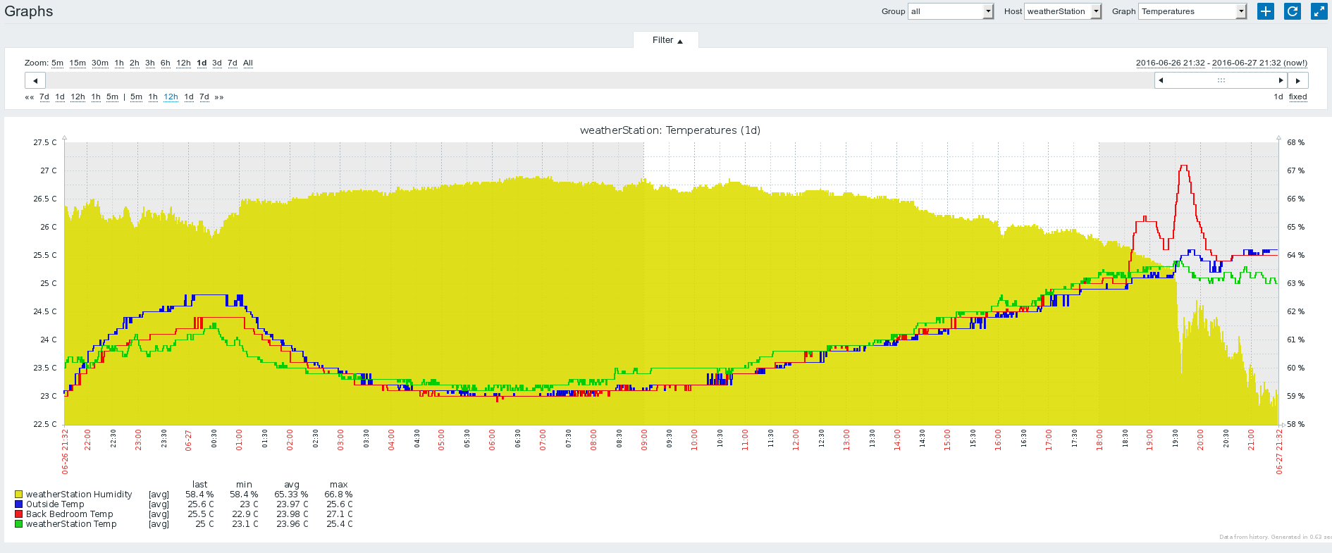
Zabbix Monitoring Integration:
QT Mobile/Desktop Application:
To Do. I would like to learn QT so I will write a application to control the station. Add sensors etc.
Video:
References:
https://www.arduino.cc/en/Tutorial/ArduinoToBreadboardhttps://www.arduino.cc/en/Main/Standalone
http://www.gammon.com.au/forum/?id=11637
https://github.com/ivanseidel/ArduinoThread
http://www.homautomation.org/2014/03/06/running-atmega328-in-a-standalone-mode-without-arduino-shield/
https://monotok.org/arduino-using-c-to-write-7-segment-4-bit-display-driver/
https://www.arduino.cc/en/Hacking/PinMapping168
http://computers.tutsplus.com/tutorials/building-a-wireless-sensor-network-in-your-home--cms-19745
https://tushev.org/articles/arduino/10/how-it-works-ds18b20-and-arduino
http://www.homautomation.org/2015/11/17/ds18b20-how-to-change-resolution-9101112-bits/
https://arduino-info.wikispaces.com/Brick-Temperature-DS18B20
https://www.arduino.cc/en/Reference/BitwiseAnd
https://github.com/milesburton/Arduino-Temperature-Control-Library/blob/master/examples/WaitForConversion/WaitForConversion.pde
http://www.hobbytronics.co.uk/arduino-float-vars
http://www.asciitable.com/
https://www.arduino.cc/en/tutorial/switch
https://forum.mysensors.org/topic/186/new-library-to-read-arduino-vcc-supply-level-without-resistors-for-battery-powered-sensor-nodes-that-do-not-use-a-voltage-regulator-but-connect-directly-to-the-batteries/2
https://forum.arduino.cc/index.php?topic=341819.0

Comments powered by Disqus.